 |
 

|
| | Electrical specifications
| Model |
HPSW VHF |
HPSW UHF
|
| Operating frequency band, MHz |
140-174 |
400-490
|
| VSWR TX, not more than |
1.3 |
1.3
|
| VSWR RX, not more than |
1.5 |
2.0
|
| TX attenuation (Insertion loss), not moredB |
0.4 |
0.4
|
| RX attenuation (Insertion loss), not more |
0.8 |
0.8
|
| Isolation, not less, dB |
40 |
40
|
| Impedance, Ohm |
50 |
50
|
| Input power, not more, W |
50 |
50
|
| Minimum response power, not more, W |
2 |
2
|
| Voltage, V |
+12 |
+12
|
| Operation mode |
dual frequency simplex (half duplex)
|
| Weight, kg |
0.62 |
0.62
|
| Dimensions, mm |
480x45x110 |
480x45x110
|
| Connectors |
N - female |
N - female
|
|
|
| |
The high-frequency switch is designed to physically separate two ports TX (transmit) and RX (receive) of one common port Rx / Tx of mobile VHF transceiver.
It is used in cases of creating a system of addition (division) of the antenna combiner on objects with a multitude of radio signals with a single antenna connector for the optimal number of antennas and for improving the electromagnetic compatibility.
The operation of the RF switch is based on the property of the PIN - diodes to pass or block the RF signal in the presence or absence of a control DC voltage. When RF power is applied, the switch automatically switches the common Rx / Tx port to the Tx OUT port. In the absence of RF power, the Rx IN port is connected to the common Rx / Tx port.
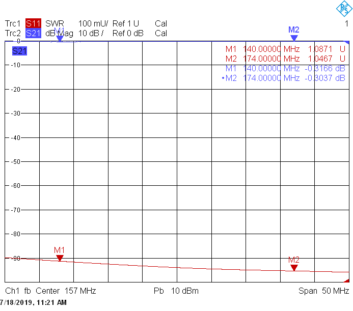
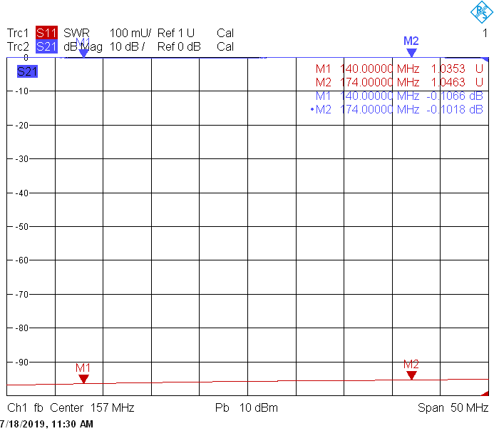
RF switcher typical gain-frequency characteristic
|
|
The information provided on this page is not an official offer.
To verify actual parameters contact the sales department before ordering.
|
|