|
 

|
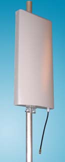
Antenna RAV-2UL-90
|
Antenna RAV-4UL-90
|
|
| | Electrical specifications
| Model |
RAV-2U-90 |
RAV-4U-90
|
| Operating frequency band, MHz |
RAV-2UL-90 |
RAV-4UL-90
|
| |
400-430
|
| |
RAV-2UH-90 |
RAV-4UH-90
|
| |
450-470
|
| VSWR, not more than |
1,5
|
| Gain,dBi |
8 |
11
|
| Sector in vertical plane , -3dB, В± 1В° |
37В° |
18В°
|
| Sector in horizontal plane , -3dB, В± 5В° |
90В°
|
| Impedance, Ohm |
50
|
| Max. power input, W |
400
|
| Lightning protection |
yes
|
|
|
Mechanical specifications
| Model |
RAV-2U-90 |
RAV-4U-90
|
| Weight not more than , kg |
9.5 |
20
|
| Radiating unit construction material |
aluminum
|
| Radome material |
ABS
|
| Radome color |
grey
|
| Standard mounting |
to 45-60 mm dia. tube
|
| Optional mounting |
wall mount or frame side mount
|
| Rated wind velocity, m/s |
40
|
| Wind loading area, m2 |
0.43 |
0.8
|
| Temperature range, В°C |
from -50 to +50
|
| Connector |
7/16 DIN (N-female optional)
|
| Size, mm |
950x400x80 |
1900x400x80
|
| |
Considered antenna provides guaranteed 90-degrees half-power radiation sector and possesses high gain due to concentration of energy in horizontal and vertical plane. Patches, implemented in this array antenna, allowed us to create low-profile panel antenna with high gain factor, and forward/backward ratio.
Antenna is protected by ABS radome with ultraviolet radiation resistant coating.
Recommended for applications like Tetra and MPT1327 trunking systems, and IMT-2000 and NMT - 450 i cellular systems.
RAV-4U-90 E-plane pattern
|
RAV-2U-90 E-plane pattern
|
RAV-2(4)U-90 H-plane pattern
VSWR diagram, RAV-2UL-90
|
VSWR diagram, RAV-2UH-90
|
|
|
The information provided on this page is not an official offer.
To verify actual parameters contact the sales department before ordering.
|
|