|
 

|
") | | Electrical specifications
| Model |
A6 UHF
|
| . |
(L)-1 |
(L)-2 |
(L)-3 |
(M)-6 |
(H)-7
|
| Operating frequency band, MHz |
403-418 |
405-430 |
412-430 |
430-450 |
450-470
|
| VSWR, not more than |
1.5
|
| Gain, dBi |
9.65
|
| Sector in vertical plane, -3dB |
12В°
|
| Impedance, Ohm |
50
|
| Max. power input, W |
400
|
| Lightning protection |
yes
|
| Adjustment |
no need
|
|
|
Mechanical specifications
| Model |
A6 UHF
|
| . |
(L)-1 |
(L)-2 |
(L)-3 |
(M)-6 |
(H)-7
|
| Weight without mounting kit, kg |
4,5
|
| Height/Length, mm |
3268
|
| Mast diametr, mm |
35-110
|
| Radome |
fiberglass
|
| Rated wind velocity, m/s |
40
|
| Wind loading area, m2 |
0.16
|
| Load of side wind 40 m/s, H |
180
|
| Temperature range, В°C |
from -50 to +50
|
| Connector |
N-female, (7/16 DIN-optional)
|
| |
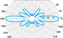
Antenna A6 UHF is a collinear construction of 11 transpositioning half-wave elements. It allows to achieve an ideally circular radiation pattern at high gain (9.65 dBi) and broad bandwidth of the frequencies of operation.
Radio transparent weather-proof radome is made on the basis of fiberglass material. The radome has a polished coating which protects from UV irradiation and icing. The antenna has a DC grounding and does not need an additional adjustment.
The model series of antennas A6 UHF (covering the range of 408-485 MHz) is used in trunking commercial and departmental networks as well as in mobile networks of the communication standard NMT 450. The antenna`s operation provides both the two-feeder type of antenna-feeder devices (AFD) (with separate feeders of receiving and transmitting channels of repeaters) and the one-feeder type that uses a duplexer.
Recently a series of these antennas has been replenished by new models specially developed for the receiving and transmitting frequencies of the most popular UHF-sub-ranges. This has allowed to use the maximum possibilities of the gain in collinear antennas in the frequency ranges of interest, in spite of their scanning.
The multimedia reels in our CD catalog reflect rather well the peculiarities of these antennas.
A6 UHF E-plane pattern
|
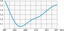
VSWR diagram A6 UHF(L)-1
|
VSWR diagram A6 UHF(L)-3
|
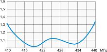
VSWR diagram A6 UHF(M)-6
|
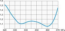
VSWR diagram A6 UHF(H)-7
|
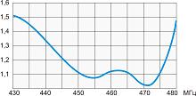
VSWR diagram A6 UHF(L)-2

|
|
|
The information provided on this page is not an official offer.
To verify actual parameters contact the sales department before ordering.
|
|